Stabilisation of the operating point 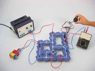 ![]()
<!DOCTYPE html PUBLIC "-//W3C//DTD XHTML 1.0 Transitional//EN"
"http://www.w3.org/TR/xhtml1/DTD/xhtml1-transitional.dtd">
Principle Negative feedback is used to increase the stability of a
transistor amplifier stage against fluctuations in temperature,
operating voltage, and scattering of characteristic amplification
quantities. This is achieved by feeding back a portion of the
output voltage to the input of the amplifier with reverse phase
position. For the negative current feedback used in this
experiment, the amplified current in the emitter resistor produces
the reverse-phase voltage (proportional to the current) used for
the negative feedback. In a negative voltage feedback, however, a
portion of the amplified voltage from the collector is fed back to
the base of the transistor.
Aside from the desired effects (increasing the stability of
the amplifier, linearisation of its characteristic curve, and
modification of its characteristic quantities), negative feedback
is always accompanied by a decrease in amplification.
The larger the ratio of feedback voltage to output voltage,
the larger the decrease in amplification.
The stabilising effect of negative current feedback can be
understood, assuming, there is a constant control voltage of, for
example, 1 V at the output of the amplifier. This is divided
between the base emitter line and the emitter resistor. Now, if the
emitter current increases due to an increase in temperature or
operating voltage, for example, then the voltage at the emitter
resistor also increases. Consequently, only a small portion of the
connected control voltage is effective for the scattering of the
transistor for the base-emitter line. This counteracts the original
increase in collector current. The same thing happens when an
alternating voltage is used for controlling. Only a portion of the
connected voltage is available for controlling the transistor when
an emitter resistor is in the circuit.
If a capacitor with a proper capacity is connected in parallel
to the emitter resistor, then the negative feedback is canceled in
the case of alternating voltage. This is not true for negative
direct current feedback, though. Benefits - No additional cable connections between the building blocks needed - clear arragned and quick setup
- Contact saftey due to puzzle blocks system
- Corrosion-free gold plated contacts
- Doubled earning sucess: Electric circuit diagram on top, real components can be seen unterside
Tasks How can a transistor amplifier stage be made insensitive to
fluctuations in operating voltage? Investigate how a transistor amplifier stage reacts when an
emitter resistor is added to the circuit. Scope of delivery |
Straight connector module, SB
|
05601-01
|
4
| |
Angled connector module, SB
|
05601-02
|
4
| |
T-shaped connector module, SB
|
05601-03
|
3
| |
Interrupted connector module with sockets, SB
|
05601-04
|
2
| |
Junction module, SB
|
05601-10
|
2
| |
Straight connector module with socket, SB
|
05601-11
|
2
| |
Angled connector module with socket, SB
|
05601-12
|
2
| |
Resistor module 50 Ohm, SB
|
05612-50
|
1
| |
Resistor module 47 kOhm, SB
|
05615-47
|
1
| |
Potentiometer module 10 kOhm, SB
|
05625-10
|
1
| |
NPN transistor module BC337, SB
|
05656-00
|
1
| |
Capacitor module 47 nF, SB
|
05642-47
|
1
| |
Capacitor module 470 µF non-polar electrolytic, SB
|
05646-47
|
1
| |
Earphones with 4mm-plugs
|
06811-01
|
1
| |
Coil, 1600 turns
|
07830-01
|
1
| |
Iron core, I-shaped, laminated
|
07833-00
|
1
| |
Connecting cable, 32 A, red, various lengths
|
07360-01
|
2
| |
Connecting cable, 32 A, blue, various lengths
|
07360-04
|
2
| |
Connecting cable, 32 A, red, various lengths
|
07361-01
|
2
| |
Connecting cable, 32 A, blue, various lengths
|
07361-04
|
2
| |
PHYWE Power supply, 230 V,DC: 0...12 V, 2 A / AC: 6 V, 12 V, 5 A
|
13506-93
|
1
| |
PHYWE Analog multimeter, 600V AC/DC, 10A AC/DC, 2 MΩ, overload protection
|
07021-11
|
1
|
|